probably I am still too much “with LtSpice” - but it must be a solution for QSpice as well (probably I don’t see the forest because of thousands of trees).
I want to determine the attenuation of a “simple” LC filter (L is in line, C is between L Output and return, followed by a resistive load) consisting parasitics. I know, not all parasitics are implemented in QSpice (such as ESL for the capacitor), however I fail with the ideal components (even with a series resistor at the input of the LC filter).
How to set up the source and how to get the attenuation to be determined across the capacitor?
Are you referring to something like this? If not, could you please post a screenshot showing how you do it in LTspice so that may provide an equivalent setup in Qspice?
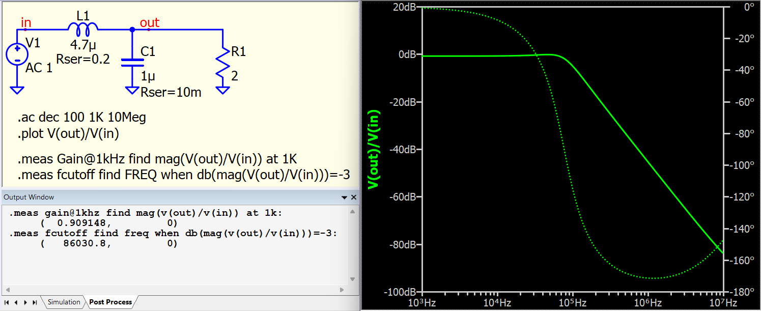
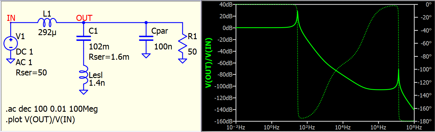
The “simple one” is like this (coming from LtSpice): L=292uH, C=102mF (note the inductor is big fat heavy, but the caps are 15 times 6.8mf in parallel which has 25mR ESR each)
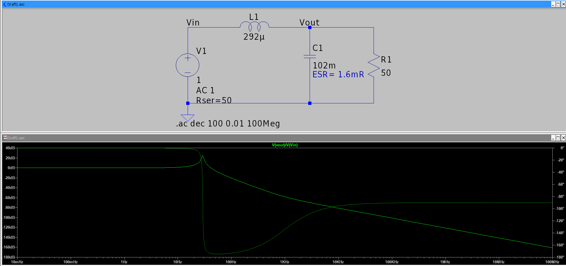
But i also want to include the parasitics (as good as possible). For the inductor I don’t know, for the capacitor I “quite” know, especially ESL (for sure, I learnt from Mike it is not foreseen in QSpice, but as it is a series component I can add it manually )
By doing this I get:
and as you can see the 40dB slope bcomes “flatten” at about 100kHz to 200kHz (which is not the case for “ideal components”). As these information are important for me I now want to get (nearly) the same result with QSPICE (and the resonance between 10 and 20 MHz is the SRF of the capacitor bank. Note, the 1.4nH is the parallel connection of those 15 caps mentioned before - and yes… it looks like EMC
relating your example - I assumed to do it like this - but my mistake was either I used a “DC source” entering a DC value with does not lead to any “expected attenuation” result or using an AC source (with all that SINE stuff) and getting no attenuation result, either. Adding the paramter AC 1 to the DC source didn’t keep in my mind (as … in LtSpice, the dialog for the source indicates it…) I think that is/was my mistake.
Thank you so far. As mentioned before … see my sentence with the forest and the trees
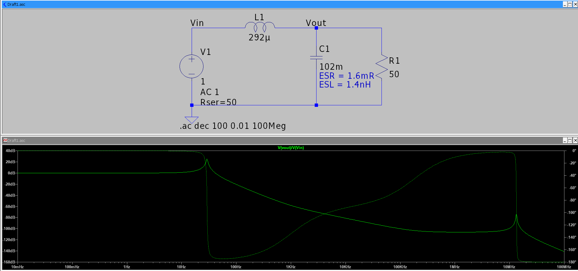
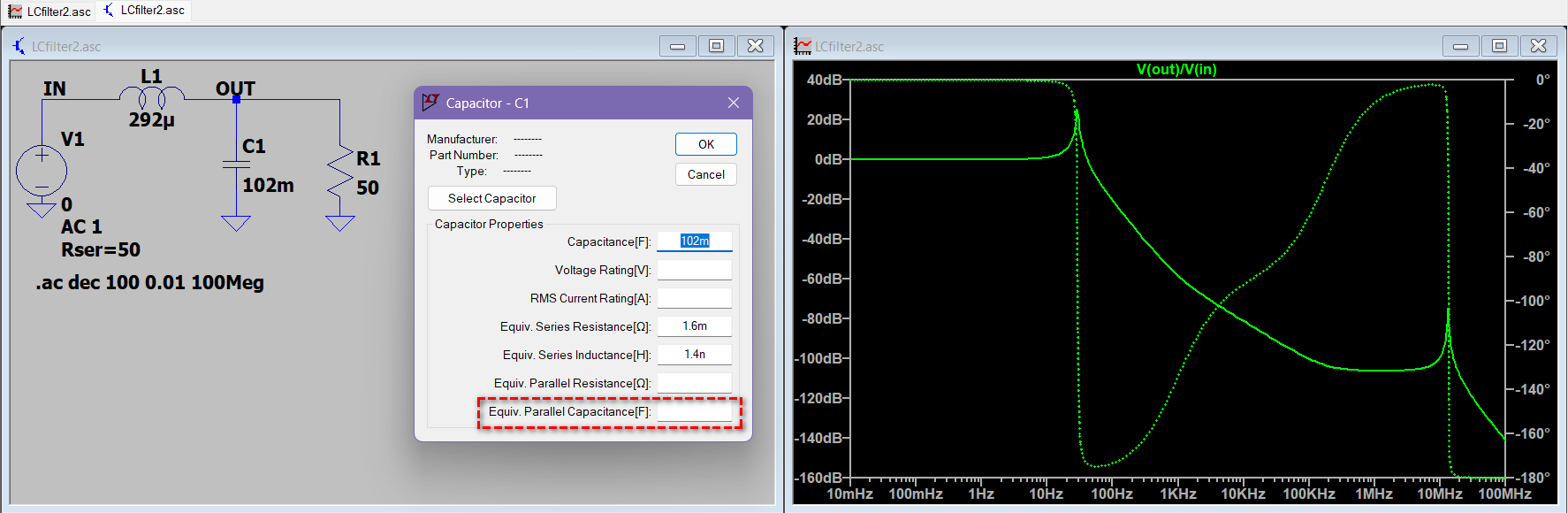
Well… I noticed something that I never aware in LTspice before. The resonance at ~13MHz in your circuit is related to an equivalent parasitic capacitance automatically added by LTspice.
If I set this equivalent parasitic capacitance to 0 to disable it, I can eliminate the resonance point.
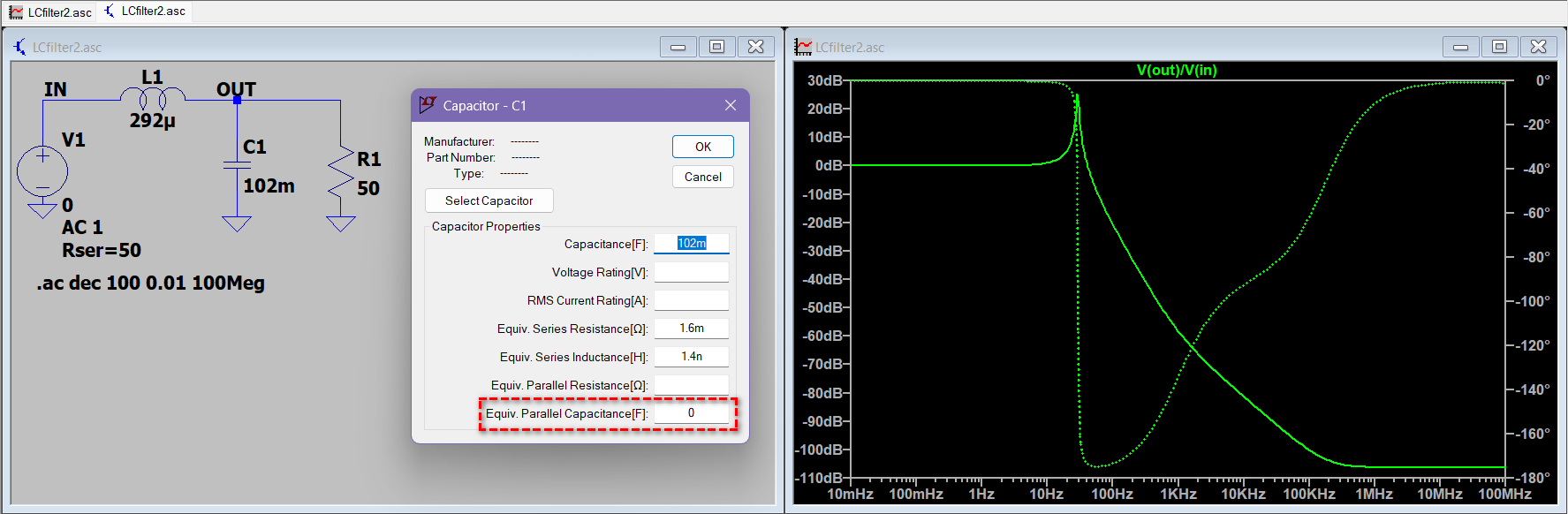
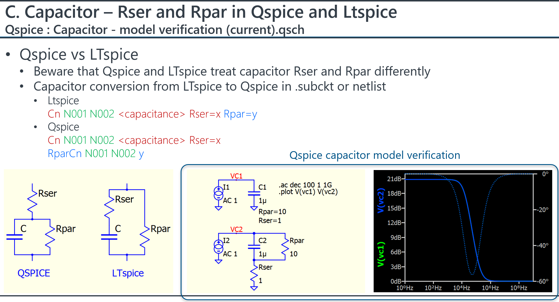
Here is a discussion topic regarding the automatic setting of Cpar when Lser is used in LTspice. This confusion would not occur in Qspice since Lser is not implemented in the Capacitor model.
Thank you for your support, Kelvin.
I assume no one is aware about that phenomenon if adding an ESL, an additional parallel capacitance is added. Probably there are some LtSPICE settings. On the other hand, a value, which is “not set” should have the behaviour being “not set” (with all consequences, i.e. not setting a resisitve value for the resistor → no simulation). However, I found the “issue” why I was not able to generate the attenuation plot (as I didn’t set the AC Attribute to the DC source)
In all SPICE, a value not set follow its default value. This also happens in Qspice. For example, inductor in Qspice in default with a finite Lpar. It is important to aware that. Goto Qspice help for more detail. Or I also have Qspice guideline in my Githib.
Based on your reply, I think your problem is resolved. Welcome to Qspice.
I agree, but it should be explained, that - when setting a parameter 1, parameter 2 is automatically set to a value x - except it will be modified.
Relating the infinite inductance: this is what I wanted to say “with all consequences” - but an open ESL for a Cap does not lead to an infinite impedance, but L=0 … Nevertheless I mark it as closed.
Thank you again, and I will have a look on your GitHub