Some questions have come up during our project evaluating various components making up an UWB positioning system. Our aim is to determine the impact the addition of a LNA, various antenna designs and an external oscillator will have on the precision.
We’d like to use the DecaRanging application for this and are wondering if there would be any modifications to the source code necessary when performing these hardware modifications. Obviously antenna delay calibration, clock trimming and such will be done.
Regarding the clock, you specify in the DW1000 data sheet that the clock has a frequency tolerance of ±20ppm, but I couldn’t find the data sheet for the clock. Would you be able to supply that or point us in the right direction?
Regarding the positioning, the ranges from each anchor has to be correlated to obtain the position. Would the easiest way to reach this be by connecting an “anchor” to a computer acting as a gateway? And does the DecaRanging perform some kind of least-squares approximation to estimate the position?
Finally, when the position is acquired - in what format is it displayed? Can you configure the anchors to create a coordinate system with a zero point at one of the anchors?
Sorry for the numerous questions, we’re currently moving away from satellite positioning towards UWB instead and trying to understand the differences.
We’d like to use the DecaRanging application for this and are wondering if there would be any modifications to the source code necessary when performing these hardware modifications. Obviously, antenna delay calibration, clock trimming and such will be done.
**DW: HW modification, like a LNA or variety of antennae would not impact the decaranging PC application. Once you keep the same processor and EVB ARM code , which you’ll need to modify, Decaranging will work.
Regarding the clock, you specify in the DW1000 data sheet that the clock has a frequency tolerance of ±20ppm, but I couldn’t find the data sheet for the clock. Would you be able to supply that or point us in the right direction?
Regarding the positioning, the ranges from each anchor has to be correlated to obtain the position. Would the easiest way to reach this be by connecting an “anchor” to a computer acting as a gateway? And does the DecaRanging perform some kind of least-squares approximation to estimate the position?
DW: PC Decaranging only measures the proximity , distance between A & B, so not the location. For location at least three range reports have to be known to determine (2d) location. TREK1000 will give you this from the box. But as you could guess , PC Decaranging cannot be used with TREK.
Finally, when the position is acquired - in what format is it displayed? Can you configure the anchors to create a coordinate system with a zero point at one of the anchors?
DW: YEP, you can. This is exactly what TREK1000 does.
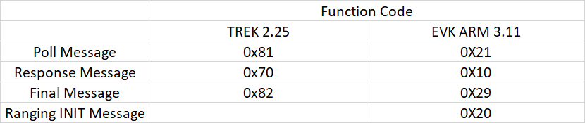
Yes, you could. But maybe start with the example code and build from there, using the TREK code as example and the source code guide. Note also , that the example code is not compatable with trek (it is with EVK), as for example the function codes are different.
But what i read, in the data sheet of the DW1000, the oscillator should have a frequency of 38.4 MHz, the one that is linked above has a frequency of 32.768 kHz. Can this be one of the clocks for the MCU (more specifically X2), as in the figure below
If one wants to test different clocks in order to increase the range and/or precision is it this clock (X2) or X1, marked in the figure below, that one should experiment with, and if so, which clock is used on the EVK1000 board?