Hmm. You can add “.param DISABLE=0” and “.param ENABLE=1” to the schematic and change the symbol attribute to “bool Enable=<DISABLE,(ENABLE)>”. Sim runs without problems and honors the selection.
I don’t disagree. However … I’m big on running stepped sims with a whole set of “what ifs”.
If I use a stepped param with lists: .step param En list 0 1
or a stepped param with lists or other increments: .step param ampgain 1 10 1
Your “CB14_Symbol2” won’t let me substitute ampgain in the place of “5” for your Gain attribute and En in the place of “1” in your Enable attribute.
Mike is using the attribute list and MIN/MAX ranging as QUX schematic pre-validations when entering the symbol into the schematic. It’s a good feature but limiting from the parameter substitution point. Therefore, if you avoid attribute lists and MIN/MAX ranging, all validation occurs when the simulation is running. The best a person can do in this case is be descriptive about what are acceptable values.
Patient: “Doctor, it hurts when I do this.”
Doctor: “Then don’t do that.”
Sorry, Len. Couldn’t resist…
Maybe share a minimal example so we can see the details? (I have this nagging thought that “EN” is the problem. I think that it may be used by other QSpice symbols.)
Edit: I tried the attached. Stepping ENABLE works for me…
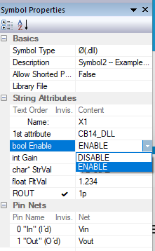
Yes, using the DISABLE and ENABLE in a stepped list works. No question because it meets the criteria on the attribute list for Enable. However, note you changed the attribute list values from 0 and 1 to DISALE and ENABLE.
Here’s the CB14_Test_Symbol3.qsch with a stepped parameterized ampgain for the Gain attribute. Now change Gain=5 to Gain=ampgain. The QUX preprocessor fails with and error and indicates the value you are entering is outside acceptable MIN/MAX limits. This is because the stepped param of ampgain gets processed when the sim is running not when the schematic is being populated. The Failure comes in the population phase. CB14_Test_Symbol3mod.qsch (3.1 KB)
Len
Here’s a modified version of your Symbol3 schematic and Symbol3 symbol.
I modified Symbol3 to get rid of the MIN/MAX range checking. This allows me to use a stepped ampgain parameter in your Gain attribute.
I also added a 2nd instance of CB14_Test_Symbol3 with the Gain attribute = ampgain*2.
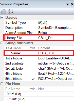
You will also notice, I deleted the original first attribute which was the name of the dll. I moved that dll name to the Libray field. Once the .cpp/dll file is created, Mike must use the dll file name as the unique function name to interface to.
You will noticed that I changed the Name field to CB14_TS1 instead of the X1. This allows me to use it as a form of descriptor and enumerator. Apparently “X” is a legacy naming convention and not strictly adhered to. Dragging the symbol into the schematic automatically enumerates the new instance and retains some descriptive abilities as well.
I thought moving the DLL name to the Library entry was interesting. It appears that, if Library isn’t blank, it is inserted before the first String Attribute in the netlist. The main difference seems to be that the Library entry isn’t displayed as an attribute in the symbol. You can accomplish the same thing by hiding the String Attribute in the symbol properties as described for ROUT in my paper.
Other than that, the netlist entry doesn’t appear to change. Since Mike didn’t put the DLL name in Library, I’m hesitant to suggest it as “better.” There might be implications that we don’t know about. (Probably not but I’ll stick to Mike’s approach until I’ve investigated further.) @KSKelvin, any thoughts?
Yes, you can change the name from X1 to something more informative. Just be sure that the last character is “1” (or at least a number) for automatic instance numbering when dropping/copying instances.
Your change to make Gain editable/parametizable is the same as the FltVal which I included to demonstrate that.
Thanks for sharing your insights, Len. I’m sure that others will benefit from the additional information.
String field Name is the device name, expected to end with a number so that when pulled into the schematic, this number can be incremented when multiple symbols are added. The Symbol Type will be added in front of this Name in the netlist if the first character of this Name does not match the Symbol Type. In short, the netlist always starts with a device whose name matches its device type at the beginning.
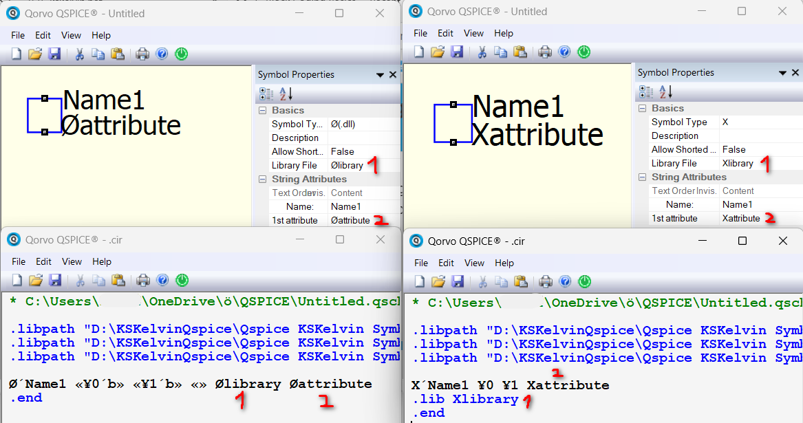
Let’s review the Library File text. For X-devices, text in the library file (not beginning with |) represents a new line in the netlist beginning with .lib followed by the text in the Library File. However, what is interesting is that for Ø-devices, it does not follow such a rule. The text in the library file immediately follows the pin definition in the netlist. This represents that if there is anything in the Library File, it takes over the position of 1st attribute.
Therefore, I cannot rule out that Mike set up the symbol in this way to allow Ø-devices to have the DLL name put into the library file. You know, the DLL name can be an absolute path of the dll file (without adding .dll, but with the full path). If anyone works with an absolute path, maybe having the DLL name in the Library File feels more reasonable.
I think it’s better to confirm with Mike if this was intentional. For myself, I prefer not to put things into the Library File in Ø-devices to have a clear workflow (I don’t like absolute path), and a meaningful description can be added with a comment string attribute, or the drawing of the symbol.
I agree we should ask Mike whether placing the DLL name in the “Library File” field is wise. (It would be consistent with the purpose of the field.)
While we’re broaching this subject with Mike … I personally like that he provided “Programmable Attributes” for symbols. It “locks in” the attribute name and type so that user of the symbol can’t change the attribute name easily. To change the name, the name needs to be altered in the symbol.
What if he provided a similar approach to the Pin Label? Right now, the user can drop the symbol onto a schematic. The user can then alter the Pin Label at will. I think it better that the pin names be consistent. While I’m at it … The other factors of the attributes can be changed such as Pin Order, Port Type, Data Type.
The thought here is that if a Ø symbol is created and shared the DLL/Verilog implementation behind it depends on some design consistency. Changing factors without some level of expertise will be, at best, confusing and, at worst, will prevent the component from running correctly.
I realize we what to encourage user customization/modification.
Suggestion: Dragging a symbol into a schematic locks in all factors except the values of attributes. Selecting the symbol and Right-click “Make Symbol Editable” allows the user to modify these factors for customization.
I realize I’m probably overly complicating things. Sorry. Just some thoughts.
@KSKelvin ,
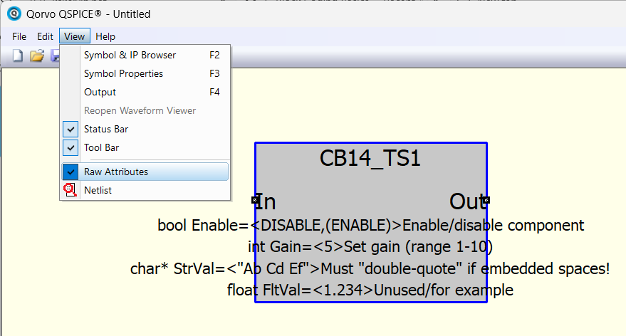
I saw the View > Raw Attributes menu selection but didn’t realize what it did.
Now I do! Thank you.
It looks like this does what I was suggesting but only for the Symbol attributes. It also allows me to get around the list and MIN/MAX pre-validation issue when placing parameter variables.
I’ve added a new document to the unplanned C-Block component series: C-Block Basics #15 – “Programmable Attributes – Lookup Symbols.” Example symbols and DLL code are included.
The paper is available on the dev branch of my QSpice GitHub repository. This is an early preview and may change before moving to the main branch.
Hopefully, you’ll find the information useful. Please let me know if you find issues or have suggestions for improvements.